Largest run-of-the-river power plant in the Alps

Infrastructure
Factbox
Client: GKI GmbH
Contractor: ARGE GKI Prutz Bau: G. Hinteregger & Söhne Baugesellschaft m.b.H, ÖSTU-STETTIN Hoch- und Tiefbau GmbH, BeMo Tunneling GmbH, Wayss & Freytag Ingenieurbau AG
Contract Type: Baumeisterleistungen
Project Type: Civil engineering/infrastructure, Tunnelling
Scope: Construction of a penstock including powerhouse and underwater channel
Construction Start: 07/2014
Construction End: 10/2018
Location: Alps (Swiss-Austrian border)
Led by Hinteregger, the GKI Prutz Bau consortium constructed a powerhouse and penstock for the River Inn joint power plant in Prutz.
The underground construction work proved particularly challenging: the team faced steep gradients and tricky geological conditions. The completed diversion hydropower plant will generate around 400 gigawatt hours per year.
Work for the Prutz construction lot began in July 2014. The boring work was completed with the last section of reverse drive in April 2018. In August 2018, following a successful pressure test, the finishing work for the reverse drive was completed. In October 2018, the structure was handed over to the client, GKI.
The power plants
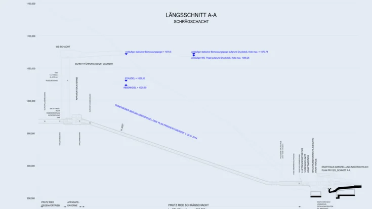
By 2021, the River Inn joint power plant (In German, Gemeinschaftskraftwerk Inn, or GKI), located on the Upper River Inn on the Swiss-Austrian border, will represent the largest new power plant in the Alps for many years. The core of the project is a weir system with a head of around 15m, and behind it a retention area with a length of 2.6km and storage space of around 900,000m³. The intake from the headrace tunnel is located on the right-hand side of the weir system, looking downstream. Up to 75m3/s of water is diverted from the retention area into the headrace for electricity generation. The water travels through the headrace tunnel, which is being developed from an intermediate heading in Maria Stein, to the nacelle, or powerhouse. It is then directed via an armoured inclined shaft (connected to a shaft surge tank on the high-water site) to two Francis turbines, which together generate power of up to 86.9 MW.
The main work in the Putz construction lot involves constructing the powerhouse, open cut construction of the underwater channel, and the underground work for the 1.5km-long headrace. The underground work includes the dismantling chamber, driving the headrace tunnel from both ends using conventional methods, building a link tunnel to the surge tank and surge shaft, the valve chamber and the inclined shaft for the penstock, including a horizontal section.
Geological conditions
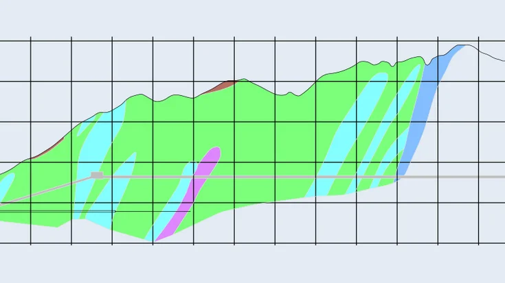
Site development began immediately the contract was awarded. The necessary roads had to be built in tight spaces while contending with challenging geology. The grey Bündner schist with sericite mica and limestone phyllites that makes up most of the Lower Engadin window is classed as brittle. While very little mountain water ingress was recorded across the whole advance area, increased water ingress was recorded in the reverse drive area from the point of transition from phyllites to calcareous slate.
Tricky tunnel advance
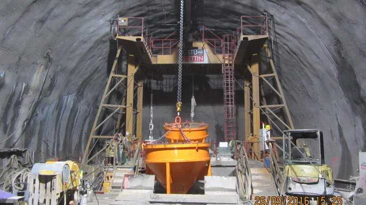
The underground construction work for the 380m long inclined shaft proved particularly challenging. The shaft, which has an incline of 31% and cross section of 23m², was driven upwards from below. The steep inclination meant the wheels were pushing their logistical limits, and a mixed system with caterpillar tracks and tyres was put in place. In order to meet the specified deadlines, the tunnel boring work was given priority, beginning at the end of February 2015. Excavation of the inclined tunnel was complete after a mere four-month construction period, with no significant problems.
The intake tunnel for the valve chamber is 290m long, with a profile of 47m². Work began in April 2015. In order to keep on schedule, parallel work started in June 2015: boring the 65m-long upper chamber bore and excavation of the 22m-long shaft head.
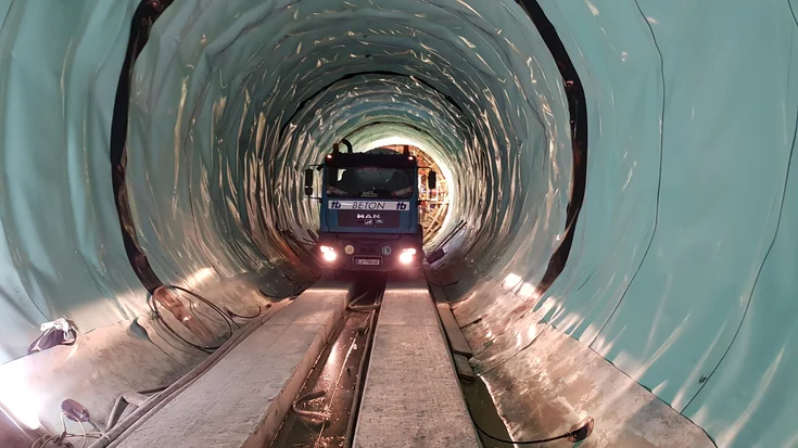
While the access tunnel was being bored close to the surface, there were numerous blast restrictions in place for protection of the local residents. This meant that at first, work could only be carried out during the daytime on workdays. Only once the boring had progressed to a pre-specified stage were additional shifts introduced. In September 2015, work began on boring the 1,000m-long headrace tunnel, which has an excavated cross-section of 43m². A conventional drill and blast process was used to bore the tunnel as far as the dismantling chamber. This was primarily due to the small curve radius – 500m – and the need for the tunnel to be sealed in the phyllite section.
In parallel with the tunnel boring, the surge shaft was erected in two phases. The first phase was the construction of a spoil shaft with excavation diameter of 1.84m, using the raise boring procedure – this involved boring a circular shaft around a pilot bore. A drilling & blasting phase then developed the cross section to its final 15.38m diameter.
Gallery


Extensive finishing work
Before cladding the headrace, the rock was consolidated with injections. In this way, the consortium was able to reduce permeability and make the stone more homogenous. In addition, compensation was made for the almost hollow stone loosened during the conventional drill and blast process, so that the original mechanical characteristics were restored. The injections were carried out in two phases, referred to as the primary and consolidation injections.
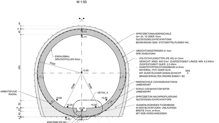
An unreinforced in-situ concrete inner shell was used to clad the headrace tunnel as far as the cone. This was sealed all around over the first 774m from the valve chamber. The remaining 230m to the dismantling chamber have not been sealed. A shotcrete interstice was built into the floor of the reverse drive bore inner shell, before the seal was installed. The aim was to end up with a virtually circular profile, since the high water pressure and potential swelling pressure would not allow for any significant deviations from the circular shape. Once the shotcrete interstice was in place, IAT GmbH installed the sealing membrane in the floor. A lime separating coat was applied in the unsealed region. In order to make the ground suitable for traffic again, the unreinforced invert concrete was installed blockwise overhead from the valve chamber in the direction of the dismantling chamber. In parallel with the concrete work, the vault was sealed during night shifts. Once the compressive strength measures described above were complete, the finished inner shell was pre-tensioned with joint injections and the pre-tensioning effects then tested using laser scanner measurements and real-time evaluation of the results.
An armoured design was used for the transition between the headrace tunnel entrance and the cone. Concrete backfill was put in behind the steel plating in the area around the inclined shaft. Despite the relatively low inclination in the shaft, the concrete backfill installed via a channel, which meant that an appropriate concrete recipe was required. Concrete supplier TB Zams carried out a large-scale test of various different recipes. This was done in the concrete factory by filling a formwork with built-in obstacles via 31%-inclined channel, matching the original, so that the flow behaviour of the concrete could be assessed. The concrete backfill work was carried out in close consultation with the third-party contractor for the hydraulic steel structures. Once the armour plating was complete, the joint injections for the construction lot were installed in both the ridge and the shrinkage gap between the reinforcement and the concrete.
The plumb shaft was clad with a reinforced, 50cm-thick concrete inner shell, sealed externally. As before, the stone was injected before sealing, and then once the inner shell was complete, a pre-tensioning injection was carried out. The inner shell was manufactured using slipform casting. The platform set-up for the poured concrete was used several times before and after the actual slipform casting as a working platform for all work being done in the shaft.
To protect the local residents, initially the access tunnel was only bored during the daytime.
P&L responsibility major projects
Underwater work for the powerhouse
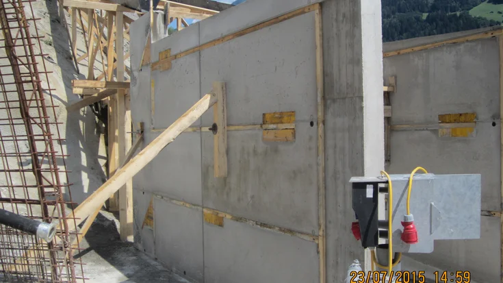
The powerhouse consists of a largely underground powerhouse shaft constructed from reinforced concrete, which plunges to a depth of 15.60m – 12.50m of this are beneath the water table. The shaft construction is surrounded by a 20m-deep diaphragm wall.
The construction pit itself was divided into three sectors; two of these have been sealed with deep-lying soft silicate gel base, while the third is sealed with a 1.20m-thick anchored slab of underwater concrete. The diaphragm wall incorporates the main structure 5m beneath the base of the construction pit and is maintained with a stranded anchor horizon. The silicate gel was installed via piped bores in a 1.95m grid in the soil.
Once the lance had been installed, first the 0.30m thick cover plate and then the entire 2.0m thick gel region were grouted in stages. The main construction area was excavated to the base of the underwater concrete slab using a dredging process. The support anchors for the base slab were installed in a 2.2m grid in the subsoil using a pile driver and piles. Once the anchors were complete, specialist divers vacuumed the fine sand around the base and placed heads on the anchors. The 1,200m³ of underwater concrete was installed via a contractor using the Hop-Dobber process.
This is a floating system consisting of a steel tremie with a collar at the lower end. The floating effect is created by a hollow body around the tremie. The construction pit was kept stable during the lancing process with a dense monitoring system. The quantity of residual water in the total 1,700m² base area was only 4.5l/s. The structural base plate was set on the underwater concrete slab, and then the blocks of the eight powerhouse levels on top of this.
Technical data
- Excavation
150.000m³
- Tunnel length
1.500m
- Diaphragm wall
10.500m²
- Surge shaft
100m
- Inclined shaft length
380m / 31% incline


