River Inn joint power plant
After conflicts with the original contractor, a consortium took over the construction of the headrace tunnel from “Maria Stein” for the River Inn power plant.
The construction site equipment was taken over from the previous contractor. The site and logistics were optimised so that the remaining project work could be completed as effectively as possible.
-
EmployerGKI GmbH
-
ContractorARGE GKI Triebwasserweg Maria Stein – Strabag/Jäger/Hinteregger
-
ArchitectBaumeisterleistungen
-
Project typeTunnel construction
-
Project scopeConstruction of a headrace tunnel using two dual-shield tunnel boring machines
-
Construction start02/2017
-
Construction end12/2020
Overview
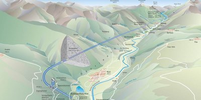
The earliest plans to exploit water power from the Upper River Inn date back to the nineteen-twenties. However, despite a number of feasibility studies being drawn up, the project was never pursued. In 2003, when planning finally began again, the project was optimised and brought up to date with the current state of the art and environmental standards.
In 2014, after a cross-border approval procedure, work began on the joint power plant on the River Inn, which will generate around 414 GWh per year. The diversion power plant covers an area of land belonging to eight different communities: seven in Austria and one in Switzerland.
Salzburg-based G. Hinteregger & Söhne Baugesellschaft m.b.H. is a member of the consortium building the 22km long headrace tunnel in the GKI Maria Stein construction section. Since the initial work on the construction section was done by a different contractor, the consortium that won the new tender had to take over the construction site set up by their predecessor – the first successful execution in Austria of an alliance contract model in infrastructure construction. Consequently, the project does not just involve driving the tunnels, but also modifying the tunnelling equipment and optimising the existing infrastructure.
This was the first successful execution in Austria of an alliance contract model in infrastructure construction.
The power station
A weir system is being built in a gorge on the Swiss/Austrian border. The head is around 15m and the retention area behind it stretches back 2.6km with a storage volume of approximately 900,000m³. A discharge power station, a fish pass and the inlet structure for the headrace are located by the weir.
Once complete, up to 75m³/s will be diverted out of the steep-sided gorge and channelled to the powerhouse via a 22km headrace that is being built from an intermediate heading in Maria Stein (Pfunds municipality). The water is then directed via an armoured inclined shaft (connected to a shaft surge tank on the high-water site) to two Francis turbines, which together generate power of up to 86.9MW.
The diversion of the torrents by the power station will bring important additional benefits in the form of improvements to the ecological situation in the River Inn. Additional compensatory and recultivation activities will further improve environmental conditions in the project zone.
Geology
The project area falls entirely within the Lower Engadine window in the Upper Inn Valley. The Lower Engadine window is part of a tectonic unit that extends longitudinally from the Austrian village of Prutz in the north-east to the Swiss village of Ardez in the south-west. In this tectonic window, the higher Austroalpine tectonic units have eroded to expose the Penninic units below. The stone exposed here is surrounded by crystalline units from the Silvretta Crystalline in the west and the Eastern Crystalline in the east.
All the areas where the TBMs are working consist of grey Bündner schist. This is primarily chalky calcareous shale with banks of marble (Ga 2.1, approx. 2.5km), pure calcareous shale or calcareous shale with pitch and graphite layers (Ga 2.2 and Ga 2.3, approx. 19km). Asbestos fibres were found in a significant part of the tunnelling sections.
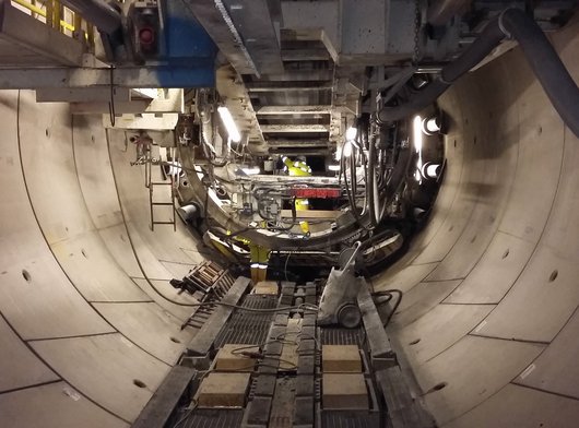

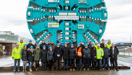
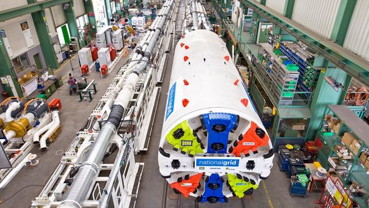
The headrace tunnel is being constructed by two identical dual-shield tunnel boring machines with excavation diameters of 6.50m working in parallel towards the north and south.
Advancing
Work on the headrace tunnel began at Maria Stein and is advancing to both the north (7,775m still to be driven) and south (10,175m still to be driven). Two identical dual-shield tunnel boring machines with excavation diameters of 6.50m are working in parallel. All site facilities have been taken over from the previous contractor and made available to the GKI Maria Stein headrace consortium, including tunnel boring machines belonging to the client, GKI GmbH. Before the consortium could begin work, the existing infrastructure had to be optimised for the remaining construction activities. The optimisation was carried out between February and April 2017, with the bulk of the work focussing on the following areas:
- TBM and trailing supports
- California switch
- Track system
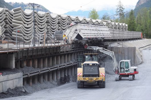
- A complete restructure in the dump area (Figure 2) where the disposal carriages are emptied
Considerable attention was given to overhauling the entire track system, since the existing system was to be used for removing the spoil by rail.

After the handover phase, the advance in the southern part of the headrace began in April 2017, when the first tunnel boring machine was started back up. The second tunnel boring machine was fired up in May 2017, beginning the advance through the northern part of the headrace. After some initial difficulties, the average advance for months when nothing unexpected occurred was around 12-19m/d.
The tunnelling work in 2017 and 2018 was held up by five long interruptions, mainly due to the shield skin getting trapped, so that the TBM had to be freed by raising the tunnel roof (Figure 4) or using special techniques such as pipe arches and injections. Following the team’s experiences in this geology, a decision was made to enlarge the overcut for both TBMs and thus reduce the risk of the skin getting trapped.


Tunnel cladding
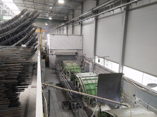
The tunnel is being clad with reinforced concrete segments. Two different types of ring are used in an open-jointed system consisting of normal rings and high-performance rings installed in parallel. Once installed, the segments will be blasted with pea gravel. The ring joints and longitudinal joints will be sealed with indented mortar joints sufficiently to prevent the cement suspension from leaking out. The mortar will be installed from the region of the TBM’s trailing supports.
The annular space will be filled with cement suspension in the area that has been bored, separately from the boring equipment. Multi-stage injections will then be carried out along the entire headrace.

Injections
The injections, intended to increase the stability and impermeability of the open-jointed tunnel segments, are a vital part of the tunnel cladding system. The goal is to create cladding that will remain stable in the specific situation with the rock and mountain water conditions on one side and the internal pressures generated by the power station operation on the other side. Headrace water is not completely separated from mountain water in this system, as would be the case with a fully impermeable lining.
The injections are carried out in multiple stages:
- Annular gap grouting – grouting the pea gravel void volume
- Contact injection – to improve segment lining bedding
- Consolidation injection – to repair areas of loose rock around the hollow space if necessary
- Sealing injection – in areas where the mountain water level falls below the internal pressure level
Monitoring bores are used to check that the injections have been successful. Due to the long length of tunnel to be driven and the agreed construction schedule, the annular gap grouting injections had to be carried out in parallel with the tunnel advance, using a single injection unit composed of four injection pumps. A self-driving portal construction was developed in order to ensure that the train removing the excavated material could travel safely through the injection area.
Material logistics
The tunnel boring and excavation works for the weir system and powerhouse will produce around a million cubic metres of spoil. The aggregate material is collected with a dredger and processed on site into concrete aggregate and pea gravel. The resulting quarry lake will be filled with uncontaminated spoil from the tunnelling work. The remaining spoil will be permanently stored in a nearby landfill. A conveyor belt transports the material to the landfill from the dump site where it is deposited by the tunnel service train.


Summary
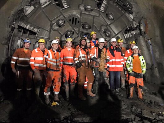
The tunnel advance began in April 2017. Exactly two years later, in April 2019, we broke through on the northern section. The southern section broke through in July 2019. The injections and remaining concrete works in the dismantling caverns and intermediate heading are expected to continue until late summer 2020. Handover to the client is scheduled for autumn 2020.

Technical data
-
Total tunnel length21,500m
-
Excavated volume610,000m³
-
Segment production9,246 rings @ 1.66m
-
Dry injection products14,200t
-
Pea gravel blasted36,800m³

